Electrical Reliability • Industrial Maintenance
NFPA 70B • Thermography
Why Experience Matters When Choosing an Electrical Thermographer
Thermographers with Plant-Electrician experience. Reporting you can act on—not photo dumps.
- Regular IR—commonly annual baseline under 70B; tighten by risk/condition.
- In-service scans with necessary covers removed; ΔT vs like reference with load % recorded.
- WO-ready findings: asset • ΔT • load % • priority • action • notes.
Plant-electrician thermographers
Independent reporting
FL · GA · AL · SC
Before
ΔT +32.8 °C
Localized heating at A & C fuse clips; load ~62% FLA, amps balanced.
After
ΔT ~0–0.6 °C

Replaced C-phase load lug + disconnect/PM; load ~93% FLA, temps even.
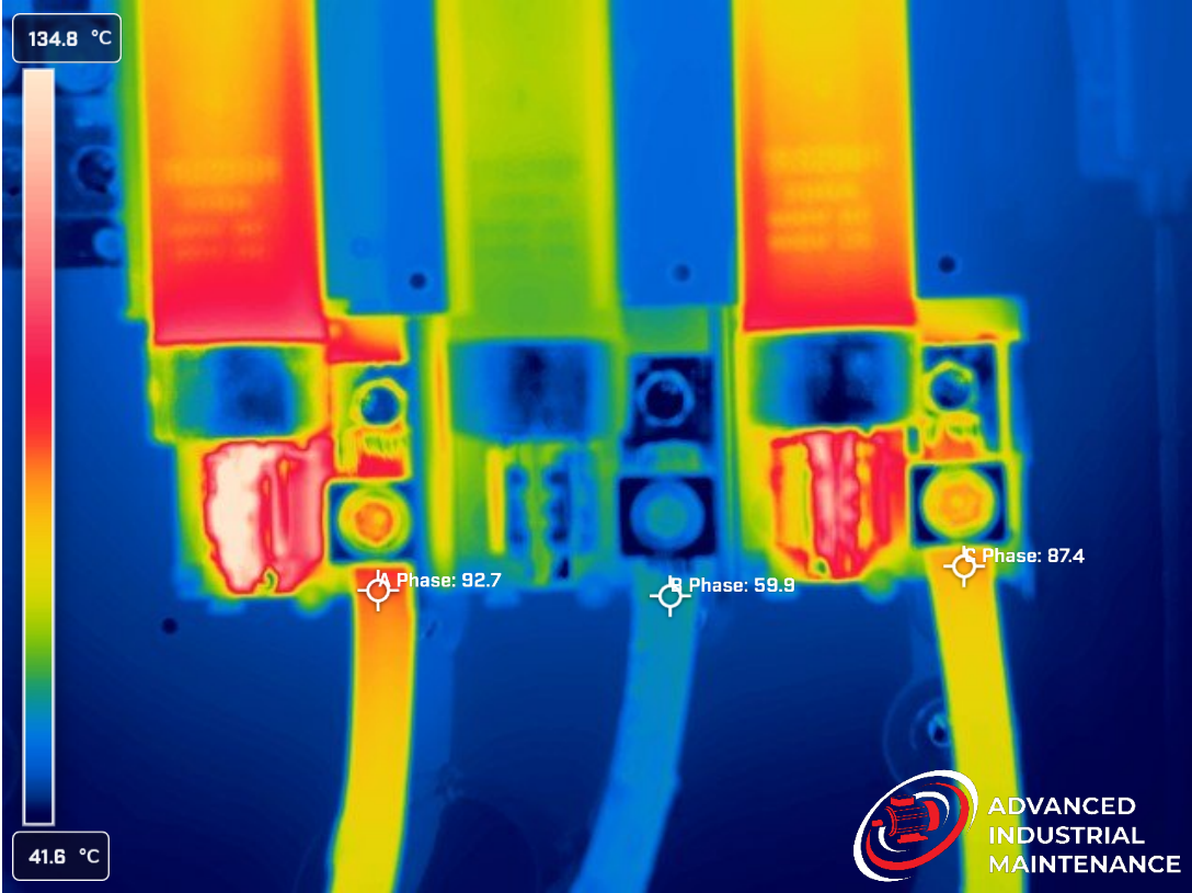
Example: Electrical Disconnect Thermogram (Before/After)
Pre-repair (finding)
Finding- Pattern: Localized heating at A & C fuse clips with clear gradient.
- ΔT: +32.8 °C vs B-phase reference.
- Load: ~62% FLA; phase currents balanced (A 87.1 A, B 86.9 A, C 87.0 A).
- Likely cause: High-resistance clip contact (loose/corroded).
Direction: De-energize; clean/retorque to spec; replace worn clips/fuses; re-inspect under normal load.
Post-repair (result)
Repaired- Load increased to ~93% FLA; temps ~30–31 °C and even; phase amps balanced (~131 A each).
- Status: REPAIRED — clip contact restored; new lug allowed meeting torque spec.
Actions performed:
1) Replaced C-phase Load Lug (couldn’t reach torque spec prior).
2) Performed Disconnect/Panel PM — clean contact surfaces, verify clip integrity, torque to OEM spec, document results.
1) Replaced C-phase Load Lug (couldn’t reach torque spec prior).
2) Performed Disconnect/Panel PM — clean contact surfaces, verify clip integrity, torque to OEM spec, document results.
Higher load but less heat. Preemptive repairs. Improved electrical reliability. That’s what you get when the thermographer understands failure modes—not just the colors on the image.
How to Vet a Thermography Provider
Use the questions below. Ask the question, compare the answer to what Good looks like, and watch for Red flags. HINT: Your thermographer should talk as much or more about electrical theory as they do thermography.
1) Plant-experience (Preferably electrical)
Ask: Have you ever worked in an industrial facility full-time? Have you installed, maintained, and troubleshot MCCs, switchgear, VFDs, transformers?
Good: Speaks plant language regarding production needs, startup and shutdown issues, maintenance schedules. Understands electrical safety, equipment lockout, control circuitry, drives, grounding, failure modes; as much theory as IR.
Red flag: Camera talk only; generic wire & conduit contractor; no plant context.
Impact if missed: May not fully recognize the needs of the plant and likely won't have a holistic understanding of the electrical system.
2) Reports written for maintenance managers
Ask: Show me a sample page.
Do they recommend solutions? Do they explain their diagnosis?
Report should include: asset ID • defect • ΔT • priority • recommended action • notes.
Red flag: Just a photo dump; vague “monitor.”
Impact if missed: You might just end up with a report full of consultant speak but little to no real guidance.
3) Heat pattern + amperage decode (I²R in practice)
Ask: A single lug shows ΔT ~+30 °C with balanced phase current—what’s your diagnosis path?
Good: Calls it likely termination resistance; references I²R (current squared), inspects pattern (localized gradient at the lug vs uniform phase heating), records amps and ΔT vs like reference, proposes de-energized verification (clean/retorque/replace worn hardware) and re-scan at comparable load.
Red flag: “Looks hot—overloaded” or “Pull new conductors” with no amperage/termination logic.
Impact if missed: Parts-swapping, repeat failure from the real loose/corroded joint, wasted window time, added exposure.
4) Diagnostic toolkit (beyond the camera)
Ask: What tools do you use to diagnose or rule out a thermal anomaly?
Good: Starts with thermal image/heat pattern, then validates with loading (phase current), phase & phase-to-phase voltage, and when relevant a power monitor/oscilloscope. Shows systems awareness (VFDs, power factor correction, transformer configuration). Mentions both energized checks and de-energized tests: contact resistance/mV-drop, insulation resistance, dissipation factor/PI where applicable, and torque verification.
Red flag: “We look at the picture and maybe check amps.”
Impact if missed: Symptom-level fixes, misdiagnosing PQ/harmonics as “bad wire,” repeat defects, and reports that don’t translate into solid work orders.
5) Conductor is hot below nameplate current
Ask: A feeder conductor runs hot below its nameplate—what top causes do you check first?
Good: Poor termination or damaged strands (lost circular mils), improper lug, conduit fill/derating, ambient/elevation, and continuous duty (NEC 80%). Verifies with mV-drop/contact resistance, torque, re-scans at comparable load, and considers imbalance/neutral current.
Red flag: “It’s overloaded—replace the conductors.” with no termination/derating checks.
Impact if missed: Unnecessary cable pulls, wasted budget, failure to fix the resistive fault, recurring heat at lugs, nuisance trips.
6) Access & safety planning
Ask: What site/PPE/permit boundaries do you operate within in scenario xyz?
Good: Demonstrates knowledge of NFPA 70E and other electrical safety considerations. Communicates their company's safety requirements and a willingness to follow yours. Also discusses coordinating with operations team to maximize equipment scanned.
Red flag: “We’ll figure it out.”
7) Optics & environmental control (prove it's a real fault, not reflected heat)
Ask: How do you confirm a hot spot isn't just an emissivity/reflectivity or focus/distance error?
Good: Discusses changing viewing angles; uses IR Target or tape/paint on shiny surfaces. talks about other thermography basics like spot-size ratio and ambient conditions - temp, humidity, wind (and more importantly, documents them in the report). Discusses comparing temperatures to similar reference as well as ambient.
Red flag: The camera says it's hot. See, right here...Hot. No verification methods, No basic safeguards...No bueno.
Impact if missed: False positives and wild goose chases. Overlooked real defects, wasted parts, time, and maintenance windows. A loss of trust in IR in maintenance and across the plant.
8) Resolution & acceptance plan (from photo to fix)
Ask: What do your findings include so we can go from photo to verified fix?
Good: WO-ready fields (asset • defect • ΔT • load % • priority • action • notes), plus acceptance criteria (post-repair ΔT threshold, torque spec & mV-drop targets where applicable), a retest plan (under comparable load), and optional repair/PM quotes with parts & task steps.
Red flag: “Monitor” or “replace parts” with no spec, no retest, no load capture; won’t touch tools or coordinate PM actions.
Impact if missed: Wasted budget, repeat faults, no proof the fix worked, and no data for future cadence decisions.
9) Avoiding common misdiagnoses (show your method)
Ask: Name three electrical IR misreads you watch for—and how you rule them out.
Good:
- Termination resistance vs. phase imbalance: Reads pattern (localized lug vs. uniform phase heating), confirms phase amps, uses ΔT vs. like reference, verifies under comparable load.
- Reflection/emissivity vs. true heat: Changes angle, applies a tape/paint dot on shiny surfaces, ensures focus & spot-size, sets proper range, documents environment (ambient, wind, humidity/DP).
- Harmonics/VFD heating vs. bad conductor: Checks THD%/waveform or neutral current when relevant, considers drives/PF caps/transformer configuration before prescribing wire pulls.
Red flag: “I can't think of any”. LOOK, there are plenty of opportunities for misdiagnosis as it is. Without full understanding of the equipment you're working on and around, there are even more chances to miss the mark.
Impact if missed: Wasted resources, a loss of trust in IR findings.